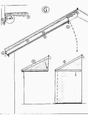
cylinder is hinge mounted—X is the hinged end of the cylinder. When a fire approaches,
the homeowner presses a button inside the house to operate an electromagnetic
catch—see S and T—and release the U end of the cylinder, which pivots to
a horizontal position. The U end of the cylinder is shown in a top-end view at
the upper left area of the G diagram. (At S is the electromagnetic door-unlocking
mechanism—as they use when George or Elaine want to enter the building in the
Seinfeld TV show—with electric wires [not shown, but symbolized with two dots]
going diagonally up towards the house's ridge.) Note that the cylinder (W) has
a triangle of blanket material fastened to it (at Y and six other places) and
the top end of this triangle of material is fastened to the house up under the
rafter at Z and other points (not shown). This means that, except for the pivot
hinge at X, the cylinder is not attached to the house at all, but, instead, to
the triangle of material which, in turn, is fastened to the rafter. So when the
U end of the cylinder is released and it pivots to a horizontal position, it
isn't finished: now its blanket unrolls completely courtesy of the force of gravity
on the weight rod (V). The homeowner fastens the blanket to the ground's
molly bolt anchors via the spring-locked hooks at U and under X. The reason the
weight rod didn't yank the blanket out of the cylinder at any time before the
fire is that when the electrically-operated cylinder-pivot-releasing button is
pressed inside the house, it releases not just the cylinder lock at S, but the
electromagnetic blanket cylinder release mechanism (see R and on a later page see
figure V) which allows the cylinder roller to turn. So the weight rod and cylinder
weight together pull down the cylinder to horizontal and the weight rod
alone pulls the blanket the rest of the way to the ground for hooking. And, of
course, the same thing happens to the right side of this end of the house. If the
cylinders were mounted just right and of just the right length, it might be
possible to have a few inches of overlap of the blankets. H. Half-deployed Fire Blanket. The weight rod will do the rest. I. Fully-deployed Fire Blanket. All that's needed is the hooking of the weight rod to the molly bolt anchors via the spring-loaded hooks. Both H and I are to be found in the G diagram above. J. Fireproof Rafter Facing Board. This will be added to all fire protection situations in which a house's rafter facing boards can be expected to be vulnerable to fire—as far as can be predicted; this means ALL situations, since none of the diagrams in this document outline methods to protect that board as well. However, one exception discussed but not diagrammed is the fence-mounted fire blanket cylinders that end up blanketing and/or shielding an entire property from fire. Therefore, in all other scenarios what's needed is a fireproof rafter facing board. |
G. Rafter-eaves-mounted Cylinder. The ends of the house have different operational
and structural needs when it comes to protection strategies. The area to
protect consists of two trapezoids, from a fire blanket point of view, one extending
from the horizontal center of the wall leftwards to the house corner, and
one extending from the horizontal center of the wall rightwards to the house
corner. Each trapezoid will be covered separately. In the figure, it appears that
the cylinder is mounted on the outside of the rafter facing board, which is
neither functionally viable nor acceptable: so the cylinder is actually mounted
on the inside of the rafter facing board and it only shows up in the figure for
purposes of illustration. (See figure K for situations—most—where there's no
room behind the rafter facing board for a cylinder; the cure is a double-wide
facing board that has a pre-mounted cylinder behind it already. This board is of
fireproof metal or other nonwood material.) The |
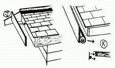
K. Board-cylinder Combination. Most facing boards will be too narrow to mount
a cylinder on, so a double-wide fireproof board with a premounted fire blanket
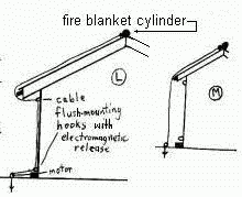
cylinder will be required. L. Fire Blanket Cable Configuration Before Release. The cables that unroll roof blanket cylinders are tucked against the house for safety and aesthetic reasons when not in use (no one needs people tripping on wires out in the open, nor does anyone wish to view them, whereas wires against house siding is standard practice for many different wiring purposes including TV cable, telephone cable, and various other types of wiring related to intercoms, alarms, etc.). There are special hooks created for the purpose of getting cables out of the way. They're called cable flush-mounting hooks with electromagnetic release. (See figures U and W.) They, like the rest of the releases and motors in the fire blanket protection scenario, are operated by use of electrical switches or buttons utilized from inside the house. They operate to free the cable from its tucked-away position by simply letting it go. Then the cable reel on the motor shaft can begin hauling in cable and unrolling the fire blanket. The blanket would stop at the top of the side of the house if the hook weren't released first. The goal is to pull the blanket straight down from the edge of the roof so there's an insulated dead air space between the blanket and the house if the fire gets as far as the blanket-no one would want boiled paint or wires on the exterior of their home if there was a way to prevent it, and that's what you'd probably get if the blanket was against the siding. |
M. Fire Blanket Cable Configuration After Release. The blanket will follow
this exact path. |


